There are no connections provided within the CHL for this function.
The best work around is to use a Solenoid Valve on the gas supply that is held open by the proving switch of the Flue or Ventilation Fan. If the fan fails, the proving switch will drop the gas supply and the water heater will fail to safe (Lockout).
The LGL GCE units are not supplied with a flue adaptor but feature common metric sizes to allow easy connection.
No, the fan on the CHL provides combustion air with just enough force to overcome the resistance of the heat exchanger. A negative draught flue is required to convey the products of combustion away.
By definition, the CHL is an atmospheric storage water heater.
Answer. If the Flue Gas Temperature Sensor sees a temperature above 70°C in the Draught Diverter, the unit will go into a blocking status (E06). When this has cooled, the water heater will try to ignite again. If the burner control logs four E06 conditions within an hour, the burner control will go to lockout, as there is a problem with the flue spilling.
The effectiveness of the flue will need to be checked and any blockages removed. If the flue is clear, the terminal position may be unsuitable or the flue run undersized or poorly routed.
E06 and F12 conditions are not problems with the water heater; it is merely reacting to a problem with the flue.
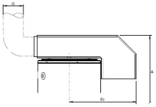
Answer. The CHL has three approved Draught Diverters: Heights detailed on page 62 of the ICM instructions. Alternatives must be ordered separately.
Supplied Type:
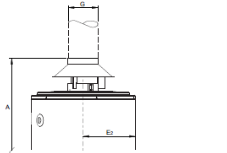
Alternative 1:
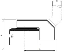
Alternative 2:
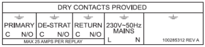
These terminals are for a common fault alarm. When the water heater goes into a fault condition, an output of 230VAC is applied to X2. X1 is a local neutral that will allow a lamp or sounder to be connected.
Unfortunately, no provision for this function is provided. It is recommended that the water heater be continuously powered up.
Remove the front casing panel and then look up at the inside of the top casing. On the front right you will find the data plate.
Over the years, there have been several engineering changes and versions of these appliances. If you are ordering any spares for these appliances, it is essential that you provide the serial number. From this, we can gain the following details on the appliance:
• If the appliance is one of Lochinvar’s
• Which electronics package and model it is
• The production number
• The week and year of manufacture
E6 is a “Safe running mode”. This is a result of the burner control seeing three high temperature differential conditions in short succession and capping the firing rate to a maximum of 50%.
This situation is usually a result of poor flow through the heat exchanger, which could be caused by:
• A Slow or partially blocked pump
• A Partially blocked or scaled up heat exchanger
• A Sudden rapid temperature drops across the cold feed/return during firing.
Once the cause of the E6 is found and rectified, it will be necessary to put the appliance into Service Mode to clear the condition.
Cascade is not a feature of the EcoForce range of water heaters.
For the Version 3 EF/EF+ units:
- Locate the small hole below the 4-pin data port on the front of the facia.
- Insert a small Allen key or pencil point into the hole and press & hold the micro button.
- This will start the appliance in Service Mode. Turning the RED thumb-wheel clockwise will run the appliance up to full rate. Turning the RED thumb-wheel fully anticlockwise will drop the appliance to low rate. The Service mode will time out after 10 minutes
For EF/EF+ BIC:
- Locate the button on the facia that resembles an archery target (service button) and press & hold it for about 5 seconds.
- This will start the appliance up in Service Mode. After stabilisation, the appliance will drop down to low rate (25%).
- Press & hold the UP arrow key until the display reads above 97%. This is considered Full rate. This can be repeated UP and DOWN. The Service Mode will time out after 10 minutes.
There have been two versions of the EcoForce to date:
• Version 3 with a three character LED display and a single RED thumb-wheel on the front. This version used the SIT914 electronics.
• EF/EF+ BIC with an LCD display and push buttons on the front. The outer casing has a red decal around the display window. This version used the BIC electronics.
Remove the front casing panel and then look up at the inside of the top casing. On the front right you will find the data plate.
Over the years, there have been several engineering changes and versions of these appliances. If you are ordering any spares for these appliances, it is essential that you provide the serial number. From this, we can gain the following details on the appliance:
• If the appliance is one of Lochinvar’s
• Which electronics package and model it is
• The production number
• The week and year of manufacture
E6 is a “Safe running mode”. This is a result of the burner control seeing three high temperature differential conditions in short succession and capping the firing rate to a maximum of 50%.
This situation is usually a result of poor flow through the heat exchanger which could be caused by:
• Slow or partially blocked pump
• Partially blocked or scaled up heat exchanger
• Sudden rapid temperature drops across the cold feed/return during firing.
Once the cause of the E6 is found and rectified, it will be necessary to put the appliance into Service Mode to clear the condition.
• Version 2 boilers can NOT be cascaded with Version 3, CPM+ or CPM ERP
• Version 3 boilers can NOT be cascaded with Version 2, CPM+ or CPM ERP
• CPM+ boilers CAN be cascaded with CPM ERP.
For version 2 or 3 CPM’s & EF/EF+ units:
- Locate the small hole below the 4 pin data port on the front of the facia.
- Insert a small Allen key or pencil point into the hole and press & hold the micro button.
- This will start the appliance in Service Mode. Turning the RED thumb-wheel fully clockwise will run the appliance up to full rate. Turning the RED thumb-wheel fully anticlockwise will drop the appliance to low rate. Service mode will time out after 10 minutes.
For CPM+ & CPM ERP:
- Locate the button on the facia which resembles an archery target (service button) and press & hold it for about 5 seconds.
- This will start the appliance up in Service Mode. After stabilisation, the appliance will drop down to low rate (25%).
- Press & hold the UP arrow key until the display reads above 97%. This is considered Full rate. This can be repeated UP & DOWN. Service Mode will time out after 10 minutes.
There have been four versions of the CPM to date:
- Version 2; with a 2 character LED display and a RED, GREEN & BLUE thumb-wheel on the front. This used SIT910 electronics.
- Version 3; with a 3 character LED display and a single RED thumb-wheel on the front. This used SIT914 electronics.
- CPM+; with an LCD display and push buttons on the front. The outer casing has a green decal around the display window. This used BIC electronics.
- CPM ERP; with an LCD display and push buttons on the front. The outer casing has a grey strike decal around the display window. The integral pump is a modulating type. This used BIC electronics.
Remove the front casing panel and then look up at the inside of the top casing. On the front right you will find the data plate.
Over the years, there have been several engineering changes and versions of these appliances. If you are ordering any spares for these appliances, it is essential that you provide the serial number. From this, we can gain the following details on the appliance:
- If the appliance is one of Lochinvar’s
- Which electronics package and model it is
- The production number
- The week and year of manufacture
E6 is a “Safe running mode”. This is a result of the burner control seeing three high temperature differential conditions in short succession and capping the firing rate to a maximum of 50%.
This situation is usually a result of poor flow through the heat exchanger which could be caused by:
- Slow or partially blocked pump
- Partially blocked or scaled up heat exchanger
- Sudden rapid temperature drops across the cold feed/return during firing.
Once the cause of the E6 is found and rectified, it will be necessary to put the appliance into Service Mode to clear the condition.
- Version 2 boilers can NOT be cascaded with Version 3, CPM+ or CPM ERP
- Version 3 boilers can NOT be cascaded with Version 2, CPM+ or CPM ERP
- CPM+ boilers CAN be cascaded with CPM ERP.
For Version 2 or 3 CPM’s & EF/EF+ units:
- Locate the small hole below the 4 pin data port on the front of the facia.
- Insert a small Allen key or pencil point into the hole and press & hold the micro button.
- This will start the appliance in Service Mode. Turning the RED thumb-wheel fully clockwise will run the appliance up to full rate. Turning the RED thumb-wheel fully anticlockwise will drop the appliance to low rate. Service mode will time out after 10 minutes.
For CPM+ & CPM ERP:
- Locate the button on the facia which resembles an archery target (service button) and press & hold it for about 5 seconds.
- This will start the appliance up in Service Mode. After stabilisation, the appliance will drop down to low rate (25%).
- Press & hold the UP arrow key until the display reads above 97%. This is considered Full rate. This can be repeated UP & DOWN. Service Mode will time out after 10 minutes.
There have been four versions of the CPM to date:
- Version 2; with a 2 character LED display and a RED, GREEN & BLUE thumb-wheel on the front. This used SIT910 electronics.
- Version 3; with a 3 character LED display and a single RED thumb-wheel on the front. This used SIT914 electronics.
- CPM+; with an LCD display and push buttons on the front. The outer casing has a green decal around the display window. This used BIC electronics.
- CPM ERP; with an LCD display and push buttons on the front. The outer casing has a grey strike decal around the display window. The integral pump is a modulating type. This used BIC electronics.
The controller may have been accessed and changed. The Digital Control Module (DCM) is indicating it is looking for a HEATPAK connected to the “BUS LINK” connections.
If no HEATPAK is connected, follow the steps below:
1. Press the “SPANNER” button.
2. Move the cursor until you find “HEATING CONFIGURATION”
3. Press ENTER.
4. Select “NOT CONNECTED”
5. Press Enter.
6. Press the “BOOK” icon button, the code should clear.
If a HEATPAK is connected, check “BUS LINK” connections at the ECH and the SHM1 Black Box
The condense pipe connection from the trap is a European size of 40mm O.D. You can get a push fit waste pipe from Screwfix (code number: 60105) which will fit into the trap. You will then need a waste pipe compression coupling (Screwfix code: 11980) to accept your solvent weld pipe.
You will need to connect the BMS or remote switch across terminals X3 and X4 (21 & 22). The switch should be “NO VOLT” and should only give or break continuity across the terminals. The Digital Controller on the EcoCharger should be set to OFF (in the main menu screen).

Yes. There are no water pressure switches or sensors in the EcoCharger so there is no minimum pressure, which will stop the appliance from working.
There are no sacrificial magnesium anodes in any of the Ecocharger models. There are Correx electronic anode systems fitted instead. The Correx anode does not deplete so will not need to be changed on a service if the Correx is working correctly. The ECH32-220GCE has only one Correx anode; all the other ECH models have two.
Press and hold the RESET and ENTER buttons together for around 5 seconds. The screen will go blank and then read, “RESET SERVICE INTERVAL SUCCESSFUL”.
Remove the front casing panel and then look up at the inside of the top casing. On the front right you will find the data plate.
Over the years, there have been several engineering changes and versions of these appliances. If you are ordering any spares for these appliances, it is essential that you provide the serial number. From this, we can gain the following details on the appliance:
• If the appliance is one of Lochinvar’s
• Which electronics package and model it is
• The production number
• The week and year of manufacture
E6 is a “Safe running mode”. This is a result of the burner control seeing three high temperature differential conditions in short succession and capping the firing rate to a maximum of 50%.
This situation is usually a result of poor flow through the heat exchanger, which could be caused by:
- Slow or partially blocked pump
- Partially blocked or scaled up heat exchanger
- Sudden rapid temperature drops across the cold feed/return during firing.
Once the cause of the E6 is found and rectified, it will be necessary to put the appliance into Service Mode to clear the condition.
Cascade is not a feature of the EcoForce range of water heaters.
For Version 3 EF/EF+ units:
• Locate the small hole below the 4-pin data port on the front of the facia.
• Insert a small Allen key or pencil point into the hole and press & hold the micro button.
• This will start the appliance in Service Mode. Turning the RED thumb-wheel clockwise will run the appliance up to full rate. Turning the RED thumb-wheel fully anticlockwise will drop the appliance to low rate. Service mode will time out after 10 minutes.
For EF/EF+ BIC:
• Locate the button on the facia that resembles an archery target (service button) and press & hold it for about 5 seconds.
• This will start the appliance up in Service Mode. After stabilisation, the appliance will drop down to low rate (25%).
• Press & hold the UP arrow key until the display reads above 97%. This is considered Full rate. This can be repeated UP and DOWN. Service Mode will time out after 10 minutes.
There have been two versions of the EcoForce to date:
• Version 3 with a three character LED display and a single RED thumb-wheel on the front. This used SIT914 electronics.
• EF/EF+ BIC with an LCD display and push buttons on the front. The outer casing has a red decal around the display window. This used BIC electronics.
Follow the procedure below:
To reset the service notification on the version 2 EKW / Herald Boiler will require a code. Please follow the steps below:
- Press and hold the L/H SELECT button
- Enter the code 5309 using the DIAL scan through the numbers and pushing the dial to accept correct number
- Press SELECT
- “Installer Code” should be displayed
- Scroll through the sub menus until you find Service notification
- Press SELECT
- Scroll to Reset Service Reminder
- Press SELECT
- It will ask you to Confirm
- Press SELECT
- You should see the word “engaged” briefly displayed.
- Press the R/H SELECT button three times to return to the front display screen
- The service notification is now reset.
When using 0-10v, the EcoKnight will be looking for a 10K NTC Tank Sensor.
If one is not fitted, most of our storage vessels feature a spare tank pocket or suitable tapping to fit one. If the tank pocket has been used by the BMS engineers, it is possible to fit a pipe sensor as close to the return tapping of the storage vessel as you can get it. This then needs to be wired back to the Tank Sensor terminals and allows the controller to see the tank temperature.
The green backlight usually indicates that the service notification has triggered. This should be reset by using the installer code 5309. If a new burner control PCB has been fitted, you will need to set the time and date, otherwise the service notification will think that it is the manufacture date of the PCB and long overdue for a service. You must also reset the service notification.
There is no Non-Return Valve in the flue. If the appliance is to be used on a common flue, it is the responsibility of the Flue Designer/Installer to ensure there is no re-circulation of combustion products through any appliances attached to the common flue.
The EKW46, EKW61 & EKW86 provide contacts to connect pumps but these are limited to what power of pump can be connected.
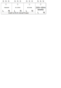
The pump terminals can only support a pump of up to 190 Watts. If the pump is of a higher rating, a suitable contactor / overload should be used. The water heater will switch the pump but it must be powered from a suitably rated external source.
The pump terminals on these models are provided as a set of “dry contacts” which are switched via a set of 25Amp relays. You will need to apply 230v power to the common terminal and connect the normally open terminal to the live of the target pump.

There is no flow switch fitted to the appliance at manufacture. It is possible to connect a flow switch by removing the link wire across the flow switch terminals.
To the right of the display window there is a small hole in the facia. Insert a small Allen key or pencil point into the hole, press and hold the micro button. The display will read “SERVICE MODE” and the appliance will start up and run up to full rate. A single push of the micro button will drop the appliance to low rate. Another press will go back to full rate etc.
The green backlight usually indicates that the service notification has triggered. This should be reset by following the steps detailed in the ICM instructions. If a new burner control PCB has been fitted, you will need to set the time and date otherwise the service notification will think that it is 01/01/2000 and long overdue for a service.
There is no Non-Return Valve in the flue. If the appliance is to be used on a common flue, it is the responsibility of the Flue Designer/Installer to ensure there is no re-circulation of combustion products through any appliances attached to the common flue.
The pump terminals on these models are provided as a set of “dry contacts” which are switched via a set of 25Amp relays. You will need to apply 230v power to the common terminal and connect the normally open terminal to the live of the target pump.
There is no flow switch fitted to the appliance at manufacture. It is possible to connect a flow switch by removing the link wire across the flow switch terminals.
To the right of the display window there is a small hole in the facia. Insert a small Allen key or pencil point into the hole, press and hold the micro button. The display will read “SERVICE MODE” and the appliance will start up and run up to full rate. A single push of the micro button will drop the appliance to low rate. Another press will go back to full rate etc.
There are no terminals provided for this function and modification of the appliance internal wiring is not permitted.
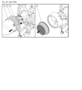
One of the main causes of this condition is a blocked air inlet filter. This is situated inside the venturi connection to the fan:
This filter must be inspected as part of the regular servicing & maintenance regime as described in the installation manual of the Eco Sable.
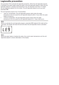
The EcoSable does not support this specific function. The EcoSable has a set point up to 85 Degrees C; which will ensure that the tank is reaching a Pasteurisation when the tank is on temperature when no draw off occurs. (during night hours for example)
You will need to connect the BMS or remote switch across the terminals on J17 of the PCB. The switch should be “NO VOLT” and should only give or break continuity across the terminals. The Digital Controller on the EcoSable should be set as follows.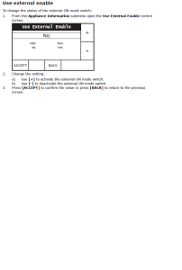
Yes. There are no water pressure switches or sensors in the EcoSable so there is no minimum pressure, which will stop the appliance working.
There are no sacrificial magnesium anodes in any of the EcoSable models. The Water Tank and Helical Heat exchanger are constructed from 316 grade Stainless Steel. Stainless steel units do not require Anode protection. Stainless Steel units are especially suited to water that has low conductivity such as naturally soft or artificially softened water. Within enamelled steel Water Heaters, corrosion could occur because of low water conductivity; which limits anode protection.
Although the appliance is in the OFF status, the internal circuitry will still have live sections. It is essential to isolate the appliance by the external switch before working on the EcoSable.
The most common cause of this is the flue temperature sensor. If the burner control does not see a temperature rise in the flue, it will cap the firing rate for safety. Check the sensor position and wiring.
Yes, there are two. They are both identical 1” anodes and have the part number: WTR2500. You will need a 33mm socket and a good drive bar to remove them.
Yes. This is detailed in the ICM instructions in section 18.0 USER INTERFACE SETTINGS > 18.4 Pasteurisation Function (using Night Set Back Facility) page 63.
The correct LPG orifice is provided within the ICM instruction packaging. It is provided for field conversion by a competent Gas Safe operative.
Yes. The heat exchanger is now secured with two unions rather than the Press-Fit pipe and fittings used in the original version.
Check the connection strip, the “24V LOUVRE COM RELAY” connections should not be used or linked.
The appliance must be in the ON status:
• Press and hold the ENTER & UP buttons together
• The appliance should start up and a spanner icon should appear in the bottom left of the display. The appliance will run up to full rate.
• Press and hold the DOWN button. The fan speed will drop to minimum rate.
• To cycle between the maximum and minimum rates, use the UP & DOWN buttons.
To exit the service mode, press and hold the ENTER & UP buttons together when the fan speed is at maximum.
Unfortunately, there is no 0-10v facility on these models.
It is possible to plug the Hot Surface Igniter cable into the Mains Power connection on the EBM Ignition Module and vice versa, accidentally.
The Power connection is at the bottom right hand corner of the module and the Hot Surface Igniter connection is top left. Once reversed, the display will come back and you will be able to put the water heater back into operation.
If you have checked the operation of the air pressure switch and found the hoses are intact and the switch clicks closed and open. It is likely that the air inlet gauze in the flue collar of the heat engine is blocked.
Take the flue off at the first collar to access and inspect this. It can be easily brushed out.
Follow the steps below:
1. Press and hold the MENU button for around 10 seconds to access the secondary parameter menu.
2. The display will read 201, it will be set as diS; press ENTER.
3. diS will now flash. Scroll through until you find Hi and press ENTER.
4. The appliance should now run at full rate.
5. To go to low rate, press ENTER and scroll the flashing value to Lo.
6. Press ENTER and the appliance should fire at low rate.
7. Cycle between the Hi and Lo until you are satisfied with the measured values.
8. To exit the service mode, scroll the flashing value to diS and press ENTER.
Normal operation will resume
Answer. The display will be showing “Src” when the service timer has timed out. To reset this do the following:
- Press and hold the MENU button for around 10 seconds to access the secondary parameter menu.
- The display will read 201, scroll to 211 (service reminder) and press
- The options are ON, OFF and rSt. Select rSt and press ENTER.
The Service Interval has now been reset.
The secondary return can be connected into the dedicated port on the side of the tank. Alternatively, it can be teed into the cold feed, which will give the full tank volume of hot water.
Either method is acceptable.
Yes. Parameter 210 is for a Legionella Purge. The factory default is OFF. Parameter 210 must be set to ON to use this function:
A remote enable should be connected across terminals X3 and X4. These terminals are “no volt” and should not have any external voltages applied to them. The enable can only be used in EXT mode:
Parameter 004 must be set to diS to switch the appliance ON & OFF remotely.
The condense pipe connection from the trap is a European size of 40mm. You can get a push fit waste pipe from Screwfix (code number: 60105) which will fit into the trap. You will then need a waste pipe compression coupling (Screwfix code: 11980) to accept your solvent weld pipe.
The electrodes in the pilot assembly are held in place by spring clips. These can be moved slightly during transport or installation. It is worth taking the burner out to check their position.
The LBF GCE does not like being direct switched (where the power id dropped to the unit). It is recommended that the black link wire is removed from terminals 18 & 19 and these are used as an enable pair. 230VAC can be taken from terminal 18, switched by a BMS or time clock and given back on terminal 19. This allows any combustion cycle that is interrupted to post purge and shut down safely.
The tube is there to remove start-up condense from the combustion chamber. There will only be a small amount of water when the appliance is firing from cold; and this will stop once the tank reaches a temperature of around 50°C. The LBF GCE is not a condensing appliance so this tube does not need to be permanently piped to the drain.
For the LBF120GCE, LBF160GCE & LBF240GCE:
The maximum length of the flue is 7m plus the terminal. In addition to the 7m, you are also allowed to use a maximum of two 45° or 90° bends within the flue run.
For the LBF320GCE & LBF382GCE:
The maximum length of the exhaust and air ducts is 7m plus the terminal. The exhaust and air ducts are allowed to use two 45° or 90° bends in each duct.
Check the wiring to the fan and air pressure switch and ensure there is no damage or loose connections.
and
Check to see if there is still a pilot flame present from the last combustion cycle. This will cause the burner control to see ionisation before it is expected. The fan will “blip” once and not start. You can test this by shutting off the gas supply for a moment (which will extinguish the pilot flame), then turn the gas back on and try again. If the appliance then proceeds to light, a new gas valve will be required.
From a thermal point of view there is not a big efficiency gain. However there is a potential energy saving from the electric element as they are interacting more with the heat pump. In addition there is a large energy saving from the hydraulic pump in the AWHA. With imperium this pump must be set at intermittent operation, making sure it doesn’t run during standby periods.
Yes. The storage tank has been designed to work with Imperium™ ensuring it has enough sensor and connection points.
For DHW the number of heat pumps is limited to 3. For CH it depends on the system type. In a system with CH only it’s 7 heat pumps (bank 2), in a combined system with 1 bank of heat pumps for DHW and CH it’s limited to 3 and in a combined system with 2 banks of heat pumps it’s 10, 3 from bank 1 and 7 from bank 2. In this kind of system the heat pumps for DHW can also be used for central heating to cover the occasional peak demand.
At the moment only with ALTUS. The controller knows the envelope (operation boundaries) and limits set points accordingly. Additional heat pumps will be added in the future.
It’s pre-programmed, easy to setup, plug-and-play and provides the possibility for one-pass/multi-pass operation
The lower anode screws into an M8 threaded receptor on the back of the cleanout door. Take note of the orientation, so the cleanout door is re-fitted correctly.
The old flue system is still available. It should be used to replace the flue like for like. The new versions of the LBF have a much lower flue exit temperature, so the flue seals and terminals are rated for lower flue temperatures and not suitable for use on old versions.
You should always replace the flue when replacing an appliance. The flue system goes through the approvals with the appliance. Even though the old flue system and new flue system are the same size and are looking good, the flue seals may well be in poor condition and may not last the lifetime of the new installed unit.
The air pressure switch might be stuck “closed”. The ignition module will not allow an ignition cycle to take place if the switch is closed on start-up. There might be some condensation in the pressure switch or its tubing. Unplug the hoses and shake out any water that might be in them. It might help if the bottom of the air switch is angled away from the water heater. This can help prevent any more condense from collecting in future.
The tube is a cable conduit that is used to feed the anode cable through when a Correx is fitted.
Yes, each of the water tanks in the range has one anode. A 27mm socket and drive bar will be needed to remove it. The replacement part numbers are:
Models LGL30 & 40GCE: LV183463023 MAGNESIUM ANODE 584MM
Model LGL75GCE: LV183463039 MAGNESIUM ANODE 991MM
Models LGL85GCE: LV183463050 MAGNESIUM ANODE 1270MM;
Yes. The Dip Tube must be fitted otherwise; incoming cold water will not force out the heated water but will pass across the top of the tank and out the hot water connection. This can also happen after many years of use if the plastic Dip Tube deteriorates.
This is common for the first start up. The water tank has to reach at least 50°C otherwise condensation will form from the water vapour in the combustion products and drip onto the burner. This should stop when the tank gets above 50°C.
The dial has five positions. These are approximate temperatures but should be as follows:
Position 1 = 30°C
Position 2 = 40°C
Position 3 = 50°C
Position 4 = 60°C
Position 5 = 70°C
You will need to pull the temperature control knob off, the burner pressure adjuster lies behind it. Attach a manometer to the test point on the side of the gas control valve to read the burner pressure.
The LGL GCE units are not supplied with a flue adaptor but feature common metric sizes to allow easy connection.
The LG GCE models have a flue thermostat that detects excess heat in the draught diverter. This is wired through a pilot interrupter on the thermocouple. If the flue thermostat activates and breaks circuit, the pilot light goes out. The reset button at the top lid (LG75&85GCE), or where the Piezo igniter is (LGL30 & 40GCE) will need to be pressed. Investigations into the effectiveness of the flue will need to be undertaken, as there has been spillage of combustion products from the draught diverter; which indicates the flue draught / flue system is not meeting the requirements.
Or
The Thermocouple has been damaged or worn out.
Or
The Water Heater requires a service, particularly around the pilot assembly.
Testing Answer
The pump has been sized to overcome the resistance of the heat exchanger. Due to this, the pump must always be sited in the return to the appliance so that water is being pushed through the heat exchanger.
The trap is located under the appliance frame near the centre. The trap must be filled with water before the appliance is fired for the first time.
The firing order might appear to be random but it isn’t. The two burner control PCB’s within the appliance are actually in a Cascade, with the upper burner being the Master. The Master will monitor the Run-Hours of both burners and sequence the firing behaviour to try and place an equal duty on the two burners.
The most important clearance is to have at least 500mm to the RH side. This is where both combustion fans are situated and space is essential to allow them to be removed if necessary. See below:
Minimum side clearance: 500mm
Minimum Front clearance: 800mm
Minimum Rear clearance: 500mm
There is a dedicated connection point in the appliance for this pump. Remove the top front cover and then the rear top panel to access the wiring centre. The connection point is located next to the main power inlet connection on the DIN rail at the top of the appliance. This can be either single or 3 phase. Refer to the ICM instructions section 11.2 for full details.